NOTE: If you get the warning about this page wanting to run scripts or an ActiveX control, it's because of a couple javascript routines to play sounds, display a cursor, or improve navigation. There are no ActiveX routines associated with this page. I don't do viruses or hacker crap, but it's your choice...You won't miss anything important by refusing permission.
page 2 - HOW TO BUILD A MODELER'S SANDING BOX
| SAFETY FIRST. Wear proper protective gear and educate yourself in all appropriate safety precautions before working with the tools and materials.
|
IMPORTANT NOTE
For an illustration of the major components, see the CG exploded view.
Because not everyone will be using the tools and materials I chose, I've made a separate Tools and Techniques section. There you will find a discussion of the specifics of cutting the box joints and forming the baffle.
If you decide to follow the steps and use the specified materials, I've provided full-sized patterns. These contain the dimensions of the various components. The baffle was the most problematic component to design and the pattern will save you considerable time. If you've decided to use alternate materials or change any of the dimensions, be sure in measuring that you have taken into account such things as the flanges of the top and baffle, thickness of the wood, depth of the dadoes, the type of joining, etc.
Though the baffle introduces some complications to the construction, the added difficulty was not beyond my novice skills and required no special tools aside from metal snips. The effort was worthwhile; I believe the baffle contributes to the operating efficiency of the sanding box.
The following instructions generally assume that you are using the provided pattern.
STEPS
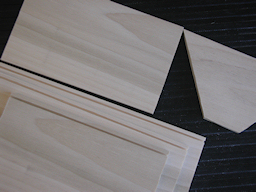
- Start by cutting the wood for the sides of the box and the trapezoidal internal baffle brace (trapezoid). [NOTE: All dimensions are contained in the patterns.]
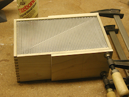
- Dado slots in the sides and one endpiece. Leave the other endpiece without a slot. The slots are 1/8 inch from the edge of the piece and their depth is 1/8 inch. These slots need to be wide enough to accomodate the combined thickness of the perforated aluminum top and the edges of the internal baffle, and deep enough to securely hold the work surface. The blade I used (24 tooth, tungsten carbide tipped) conveniently has a 1/16 inch kerf.
|
|
|
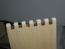
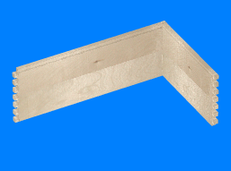
- Cut the box joint tenons. If you've never done these before (and this was my first attempt) study up carefully beforehand and make sure you understand the procedure. Remember: SAFETY FIRST. For more information, see the Tools and Techniques section of this tutorial.
- Test fit the pieces, but don't glue them yet.
|
 |
|
- Cut the aluminum for the baffle.
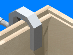
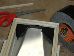
- With a metal straightedge, bend the aluminum where the pattern indicates "crease". Place the wide end of this aluminum piece centered over the narrow end of the wooden trapezoid and form the aluminum to it's final shape. For a visualization of what that shape should be, click and drag on the image to the right.
- Carefully bend the long edges of the baffle so that they form smooth flanges which fit easily into the slots of the sides and the one endpiece. [This will likely involve repeated test fitting and trimming.]
|
 |
|
- If you've disassembled the box, again test fit (but do not glue) both endpieces and the sides of the box together.
- Place the trapezoid inside the box against the endpiece without the slot. Align the top edge of the trapezoid so it exactly matches the bottom edge of the dado slots on both sides. Clamp the trapezoid in place, disassemble that end from the box, mark the trapezoid's position on the endpiece, apply some wood glue and secure these two pieces together. Set this assembly aside to dry.
[Some of the following will be CG images. Technical problems caused loss of some of the photos and I had to quickly improvise.]
|
|
|
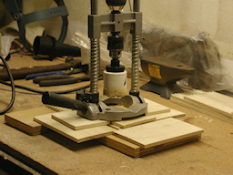
- When the endpiece and trapezoid are bonded, measure the diameter of the vacuum hose fitting and cut a matching diameter hole through the endpiece and trapezoid assembly. This hole should be centered within the trapezoid.
|
|
|
- Glue and assemble the endpiece (without the hole) to one of the sides. Make certain these are at a ninety degree angle. It's best to use a corner clamp for this operation.
- Test fit, but do not glue, the endpiece/trapezoid assembly (hereinafter: fitting endpiece) and the remaining side. Clamp them as necessary and leave them in place for the next step.
|
|
|
- Cut the stringers for the bottom of the box. I used 1/4 inch square basswood stock.
- Cut the box bottom. I used 3/16 inch birch plywood, but any comparable narrow thickness material will do.
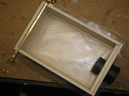
- Put some wax paper over the bottom piece and place the box over it. [The wax paper keeps glue seepage from getting on the bottom piece in step 17 (below).]
- Check the thickness of the bottom material and the depth of the stringer directly beneath the trapezoid. When this stringer and the fitting endpiece are glued in place, there must be a gap sufficient to allow the baffle to slide easily into place between the top side of the stringer and the bottom edge of the trapezoid. If necessary, trim away some material from the top side of the stringer.
- Apply glue to the sides of the stringers, position them inside the box resting on the bottom piece and secure them in place until bonded.
|
 |
|
- Remove the unglued fitting endpiece and side.
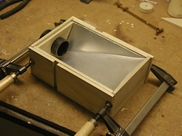
- Slide the flanges of the baffle into the matching slots of the glued side and endpiece assembly.
- Test fit the unglued side. Trim the aluminum or perform any other necessary adjustments until everything fits correctly. Then test fit the fitting endpiece and again do any necessary trimming.
- With the fitting endpiece in place, the large end of the baffle should fit snugly around the bottom three edges of the trapezoid.
|
 |
|
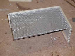
- Cut the perforated aluminum for the work surface.
- Remove the unglued fitting endpiece and side.
- Leave the baffle in place and slide the perforated aluminum piece (over the baffle) into the same slots.
- Test fit the unglued side. Trim the aluminum or perform any other necessary adjustments until everything fits correctly. Then test fit the fitting endpiece and again do any necessary trimming.
|
|
- When you can easily complete the assembly, apply glue to the tenons of the side for the joint that meets the endpiece and clamp it into place, again being careful to keep the joints square. Leave the unglued fitting endpiece in place for this step.
- When the side joint is dry, remove the fitting endpiece, apply glue to its tenons and clamp it in place.
|
|
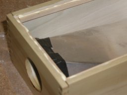
- Looking at the assembled box from the bottom, check for any large gaps between the edges of the baffle and the trapezoid. These should form a tight seal. If they're snug, you could apply a bead of silicone sealer. Because my assembly was a prototype, there was a noticeable gap between the trapezoid and edges of the baffle. I decided to seal this with Gorilla Tape. Not elegant, but I figured...What the heck, nobody's going to see it. (oh, wait...damn)
|
 |
|
- Apply glue to the bottoms of the stringers and attach the bottom of the box.
- If needed, lightly sand the inner edges of the box above the work surface, to round them slightly. The poplar was milled well enough that on my unit this was not really necessary.
- If desired, varnish or stain the box.
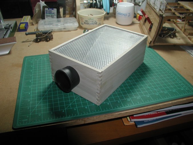
- Insert the vacuum fitting tube. In my unit, the fit was snug enough that no adhesive was necessary to keep the tube in place regardless of traction from the vacuum hose.
|
 |
| |
Amazing. It looks just like real life.
But wait! There's more!...


All original contents copyright bilagaana. All rights reserved.
This page uses the optional Paddington font.