PROLOGUE
Before we begin our discussion, a word about terminology:
The RD5 Manual uses the term "points" interchangeably to describe a number of different things associated with Bezier curves: Corner Points, Curve Points and Control Points. Unless you are the author of this section of the manual or extraordinarily alert, this quickly becomes confusing.
According to the manual:
Corner Points are Bezier vertices without handles (i.e.: with the handles retracted).
Curve Points are Bezier vertices with handles extended.
Control Points are the knobs on the ends of those handles which extend out from a Curve Point.
In an attempt to reduce confusion, this discussion will use only the following terms:
Cross-sections are one of the most useful features of the Free Form Modeler. Cross-sections are Bezier curve objects on the Drawing Plane.
Except for the simplest geometric forms, it can be difficult to produce smooth, symmetrical cross-sections by manually editing the Bezier curves that make up the cross-sections. If you've worked with RD5 for awhile and tried to create precision models you know that repositioning nodes and control points by eye, using a mouse or trackball, is an exercise in frustration.
This is a discussion about the use of the Properties Window to control the position of nodes and control points. It will cover the tools and techniques for creating perfectly symmetrical cross sections.
USING THE PROPERTIES WINDOW
Note: Unfortunately, RD5 does not allow the use of the Properties window to directly edit the nodes or control points of sweep paths or extrusion envelopes. This feature is only available for the drawing plane. You can, however, see the numeric values displayed and use them as a guide for manual editing.
I'm going to use a symmetrical cross-section from one of my projects as an example. You will get more out of this discussion and avoid some confusion if you start RD5 and create a similar cross section as we go along.
Now, for fun, try to create as nearly perfect a symmetrical cross-section as you can using visual approximation--adjusting the position of the nodes and control points by eye using the mouse. For the purposes of this discussion, it should look something like the following illustration:
Now we're going to access the Properties window and begin to edit the cross-section:
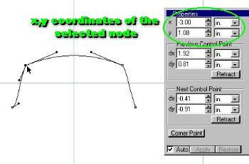
Notice that the Properties window gives x and y coordinates of the node. Don't get confused here--x and y in this case are the same as x and z would be if the three-dimensional axes convention used everywhere else in RD5 were in effect. Here, it's treating the drawing plane as a simple Cartesian (x,y) coordinate system: x is the horizontal component and y is the vertical.
This brings us to the useful feature of the Properties window: The ability to directly enter x,y coordinates. Go ahead and enter identical coordinates for the two nodes (except for the signs--positive or negative--which should remain the same as those of the original values found in the x,y windows).
Below the x,y coordinates are two areas labeled "Previous Control Point" and "Next Control Point." Remember: here, control points are the little black knobs on the ends of the handles extending from a node. The Previous and Next windows are showing data associated with the pair of control points attached to a single node.
So, now the first question we need to answer is: Which is the Previous Control Point and which is the Next? We'll use a simpler cross-section to illustrate:
Working counter-clockwise around the circle, the first control point encountered is the Previous, and the one immediately counter-clockwise from it, past the node, is the Next point.
It is just a bit less obvious which is which when using open, oddly-shaped cross-sections. However, visualizing the nodes as being on the surface of a circle helps straighten out the confusion.
1. Node Positions
The utility of editing the x and y positions of the node is fairly obvious--if two nodes need to be symmetrically spaced on either side of the origin, all that needs to be done is directly enter the coordinates--identical in x and y directions except for their respective signs--positive or negative.
This works so long as the cross-section is centered on the drawing plane [Sections/Center]. If your object requires that the cross-section be displaced from center, you'll need to keep track on a piece of paper of the relative displacements of the nodes on the x and y axes.
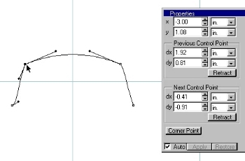
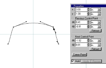
The following two illustrations are of a centered cross-section. Notice the x,y values of the left and right nodes:
 |
 |
2. Control Point Positions
Using the Previous and Next control point functions is a bit less obvious than using the node coordinates.
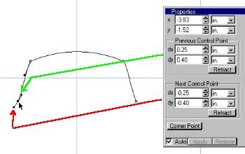
The terms "dx" and "dy" are standard mathematical notations for the "difference" or "change" in x and y, respectively. Here, they represent the displacement (in the x and y directions) of the respective control points from their associated node. That is, how far they are in the x and y directions from the node to which they are attached--not their positions on the global x,y plane itself. Therefore, these values do not locate the control point on the plane, as do the values for the nodes.
In the illustration below, a smooth, symmetrical curve was desired, so the dx and dy for both the Previous and Next control points are identical; i.e.: Their displacements about the node are identical in both the x and y directions, differing only in their signs.
 Bottom Left Node
I wish I could tell you how the positive and negative signs are assigned but, after much experimentation, no consistent pattern has emerged. This makes no sense, of course; there must be a pattern since this is a computer. The best that can be suggested at the present time (until some new insight strikes) is to experiment with whatever set of points you are editing at any given time and make note of how the signs change as you manipulate the control points.
One other thing to take note of, and you'll need to read this carefully, because it's confusing at first:
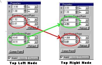
Refer to the set of illustrations above labeled "Top Left" and "Top Right" nodes, and the illustration following this paragraph. Notice the values for the control points. The left-side Previous Control Point's values are found (with the required change in signs) in the right-side Next Control Point's windows. Likewise, the left Next point's values are transposed into the right Previous point's windows (again with changes in signs). Symmetry is achieved by making the two nodes and their control points mirror images of each other.
All of this is confusing, at first. As always, the best way to get comfortable with this technique is to use it for one of your own projects. It quickly becomes indispensable, especially for highly detailed models.
All constructive comments, suggestions, and corrections are welcomed.
All contents copyright 1998-2000 bilagaana. All rights reserved. The images may not be copied in any form without the permission of the author. Digitally watermarked.